Control discarded copier and tape drive-style displays with Arduino
As hardware hackers, we’re always on the lookout for discarded components that can be re-purposed into something even more awesome. One such class of component that you may find is the controllerless graphics LCD modules, which can be found on old copiers, tape libraries, and the like.
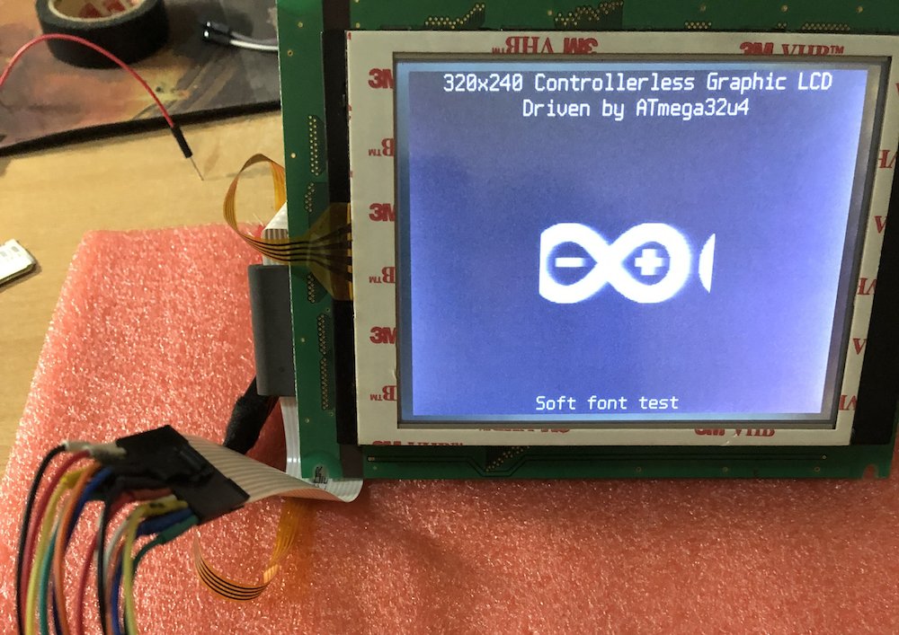
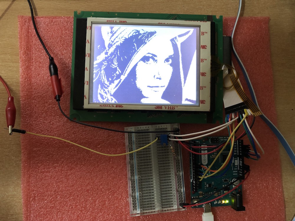
This project by Ivan Kostoski shows how to drive one of these displays with a 320×240 resolution. He’s tested his code using several types of Arduino board, such as the Uno and Leonardo, using minimal external components.
Summary
Repository contains code samples for driving 4-bit parallel controllerless graphics LCD (CLGLCD) module with AVR MCU on an Arduino board, using minimal external components and staying within Arduino IDE.4-bit Controllerless Graphics LCD modules
Controllerless graphics LCD modules are antiques that can be salvaged from old copiers, tape libraries, etc… They commonly are missing, well, the controller chip, the one with the memory. Don’t go buying one of these, for Arduino usage, even if you find them on sale. They are usually industrial, have poor viewing angles, generally slow response time, and pain to work-with. There, I said my peace… But if you already have one, their size (i.e. 5.7in) or simplicity can have its uses and beauty.I have tested this code with 320×240 STN LCD monochrome module marked as F-51543NFU-LW-ADN / PWB51543C-2-V0, salvaged some time ago from retired tape library, without the controller module (which it appears is based on FPGA and wouldn’t be of much use anyway).
The same type of interface (4-bit data) with various signal names is present on many industrial modules based on multiplexed column and common row LCD drivers, like LC79401/LC79431. Or this is what is behind the controller IC. They all have some variations like LCD drive voltage (positive or negative, depending on temperature and size of the module), backlight (LED/CCFL), some logic quirks (i.e. CL2 is ignored while CL1 is up, etc…), so maybe this code can be adapted to other controllerless modules. Module’s datasheet is necessity for the connector pinouts and timing requirements. Some modules may even generate LCD drive voltage internally, and outputting it on a pin so actual V0 driving voltage can be adjusted.
More info on the build/technique is found on GitHub, where you can also download project code and find more background on how interfacing with these devices works.