Machine vision with low-cost camera modules
If you’re interested in embedded machine learning (TinyML) on the Arduino Nano 33 BLE Sense, you’ll have found a ton of on-board sensors — digital microphone, accelerometer, gyro, magnetometer, light, proximity, temperature, humidity and color — but realized that for vision you need to attach an external camera.
In this article, we will show you how to get image data from a low-cost VGA camera module. We’ll be using the Arduino_OVD767x library to make the software side of things simpler.
Hardware setup
To get started, you will need:
- Arduino Nano 33 BLE Sense with headers
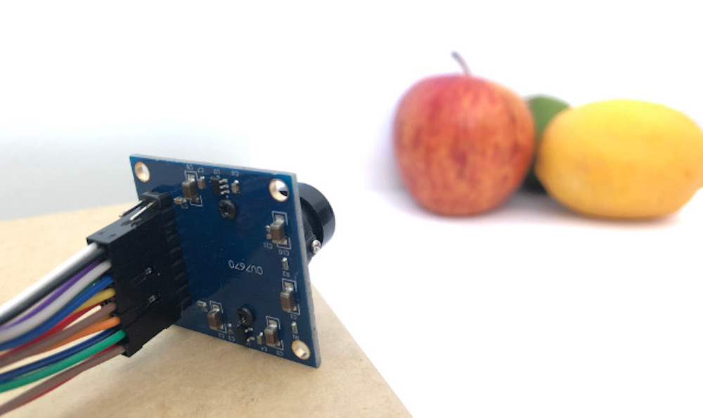
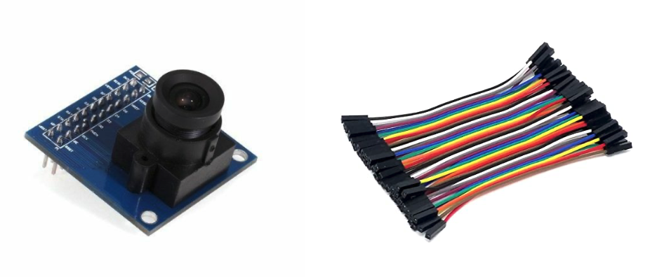
- OV7670 CMOS VGA Camera Module
- 16x female to female jumper wires
- A microUSB cable to connect to your Arduino
You can of course get a board without headers and solder instead, if that’s your preference.
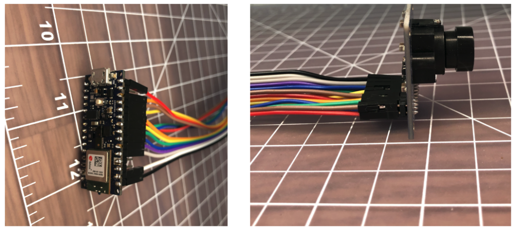
The one downside to this setup is that (in module form) there are a lot of jumpers to connect. It’s not hard but you need to take care to connect the right cables at either end. You can use tape to secure the wires once things are done, lest one comes loose.
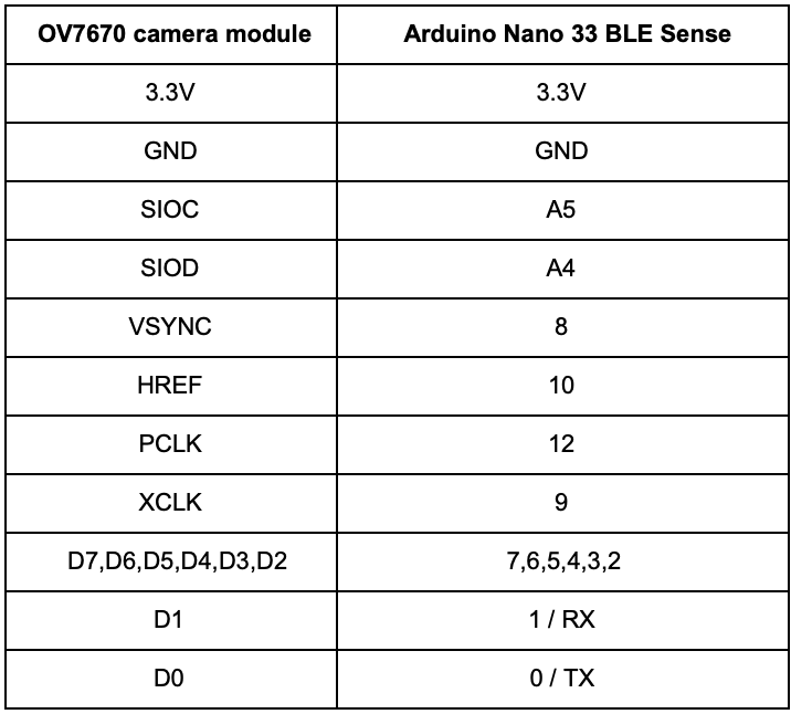
You need to connect the wires as follows:
Software setup
First, install the Arduino IDE or register for Arduino Create tools. Once you install and open your environment, the camera library is available in the library manager.
- Install the Arduino IDE or register for Arduino Create
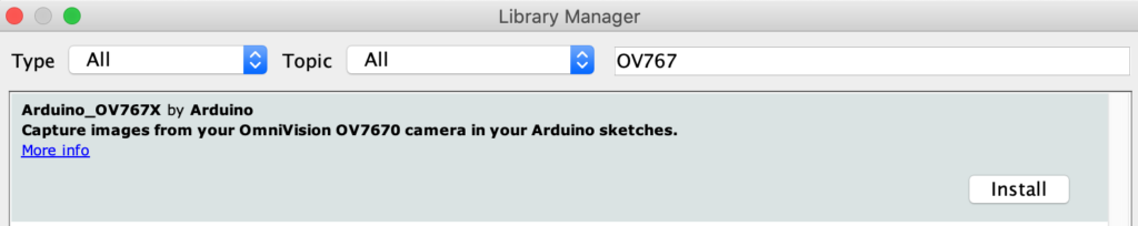
- Tools > Manage Libraries and search for the OV767 library
- Press the Install button
Now, we will use the example sketch to test the cables are connected correctly:
- Examples > Arduino_OV767X > CameraCaptureRawBytes
- Uncomment (remove the //) from line 48 to display a test pattern
Camera.testPattern();- Compile and upload to your board
Your Arduino is now outputting raw image binary over serial. To view this as an image we’ve included a special application to view the image output from the camera using Processing.
Processing is a simple programming environment that was created by graduate students at MIT Media Lab to make it easier to develop visually oriented applications with an emphasis on animation and providing users with instant feedback through interaction.
- Install and open Processing
- Paste the CameraVisualizerRawBytes code into a Processing sketch
- Edit line 31-37 to match the machine and serial port your Arduino is connected to
- Hit the play button in Processing and you should see a test pattern (image update takes a couple of seconds):
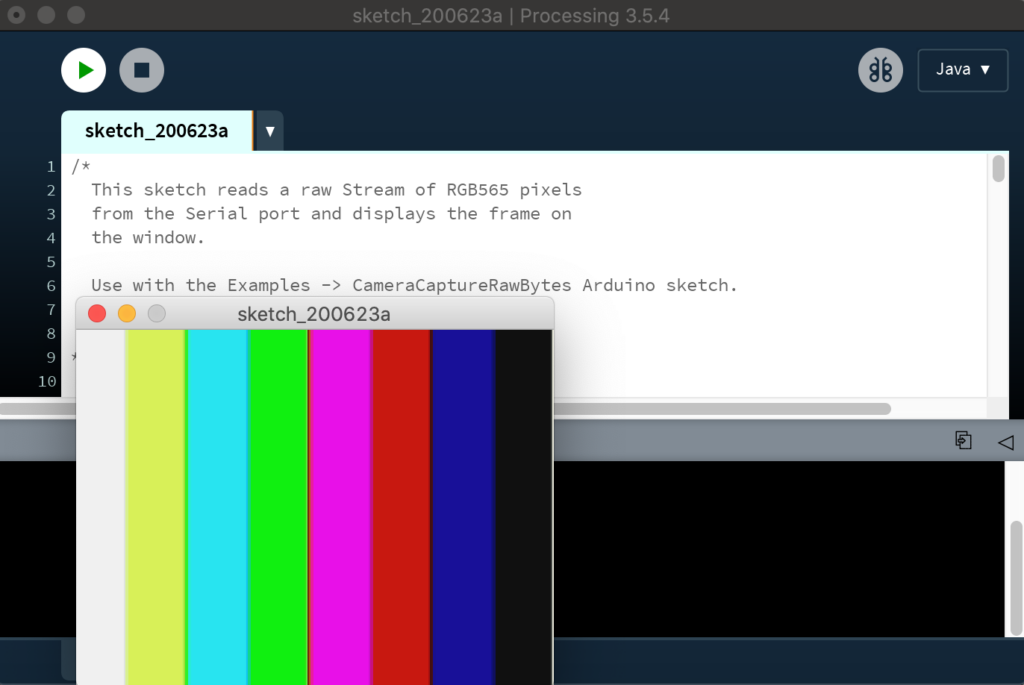
If all goes well, you should see the striped test pattern above!
Next we will go back to the Arduino IDE and edit the sketch so the Arduino sends a live image from the camera in the Processing viewer:
- Return to the Arduino IDE
- Comment out line 48 of the Arduino sketch
// We've disabled the test pattern and will display a live image
// Camera.testPattern();- Compile and upload to the board
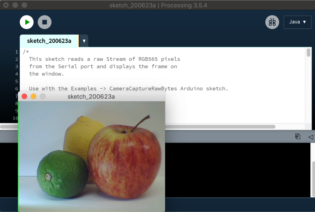
- Once the sketch is uploaded hit the play button in Processing again
- After a few seconds you should now have a live image:
Considerations for TinyML
The full VGA (640×480 resolution) output from our little camera is way too big for current TinyML applications. uTensor runs handwriting detection with MNIST that uses 28×28 images. The person detection example in the TensorFlow Lite for Microcontrollers example uses 96×96 which is more than enough. Even state-of-the-art ‘Big ML’ applications often only use 320×320 images (see the TinyML book). Also consider an 8-bit grayscale VGA image occupies 300KB uncompressed and the Nano 33 BLE Sense has 256KB of RAM. We have to do something to reduce the image size!
Camera format options
The OV7670 module supports lower resolutions through configuration options. The options modify the image data before it reaches the Arduino. The configurations currently available via the library today are:
- VGA – 640 x 480
- CIF – 352 x 240
- QVGA – 320 x 240
- QCIF – 176 x 144
This is a good start as it reduces the amount of time it takes to send an image from the camera to the Arduino. It reduces the size of the image data array required in your Arduino sketch as well. You select the resolution by changing the value in Camera.begin. Don’t forget to change the size of your array too.
Camera.begin(QVGA, RGB565, 1)The camera library also offers different color formats: YUV422, RGB444 and RGB565. These define how the color values are encoded and all occupy 2 bytes per pixel in our image data. We’re using the RGB565 format which has 5 bits for red, 6 bits for green, and 5 bits for blue:
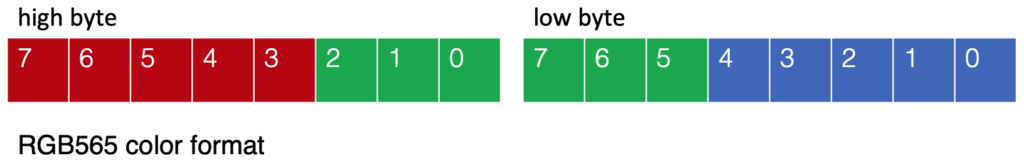
Converting the 2-byte RGB565 pixel to individual red, green, and blue values in your sketch can be accomplished as follows:
    // Convert from RGB565 to 24-bit RGB

    uint16_t pixel = (high << 8) | low;

    int red   = ((pixel >> 11) & 0x1f) << 3;
    int green = ((pixel >> 5) & 0x3f) << 2;
    int blue  = ((pixel >> 0) & 0x1f) << 3;
Resizing the image on the Arduino
Once we get our image data onto the Arduino, we can then reduce the size of the image further. Just removing pixels will give us a jagged (aliased) image. To do this more smoothly, we need a downsampling algorithm that can interpolate pixel values and use them to create a smaller image.

The techniques used to resample images is an interesting topic in itself. We found this downsampling example from Eloquent Arduino works with fine the Arduino_OV767X camera library output (see animated GIF above).
Applications like the TensorFlow Lite Micro Person Detection example that use CNN based models on Arduino for machine vision may not need any further preprocessing of the image — other than averaging the RGB values in order to remove color for 8-bit grayscale data per pixel.
However, if you do want to perform normalization, iterating across pixels using the Arduino max and min functions is a convenient way to obtain the upper and lower bounds of input pixel values. You can then use map to scale the output pixel values to a 0-255 range.
byte pixelOut = map(input[y][x][c], lower, upper, 0, 255); Conclusion
This was an introduction to how to connect an OV7670 camera module to the Arduino Nano 33 BLE Sense and some considerations for obtaining data from the camera for TinyML applications. There’s a lot more to explore on the topic of machine vision on Arduino — this is just a start!