OpenGradeSIM is an open source incline simulator for indoor bike trainers
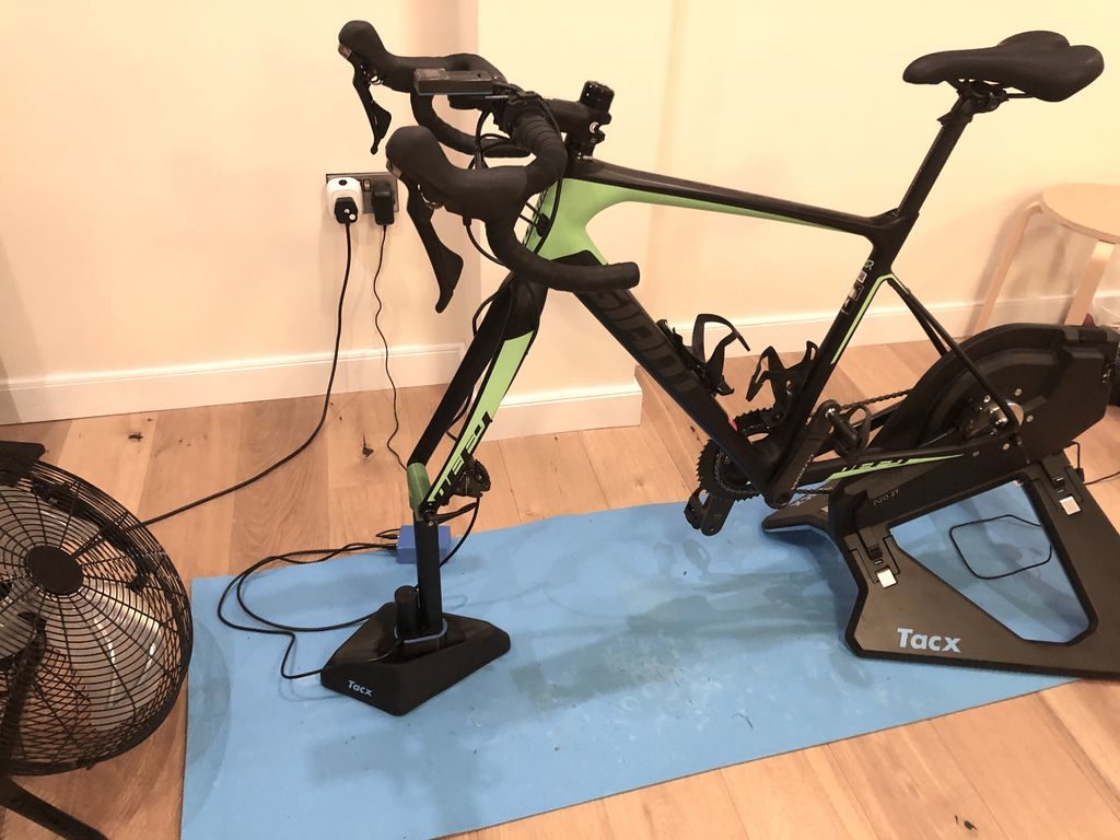
Although he would probably rather be outdoors, after an injury Matt Ockendon had a lot more time to ride his Tacx Neo indoor trainer and tinker. He decided on a rig that would enable him to physically to simulate various grades of hills; but as commercially available units with this capability are quite expensive, he instead devised his own solution dubbed “OpenGradeSIM.”
Ockendon’s setup utilizes a Nano 33 IoT to gather power and speed data from his trainer over BLE, then calculates the grade that would be needed to produce such results.
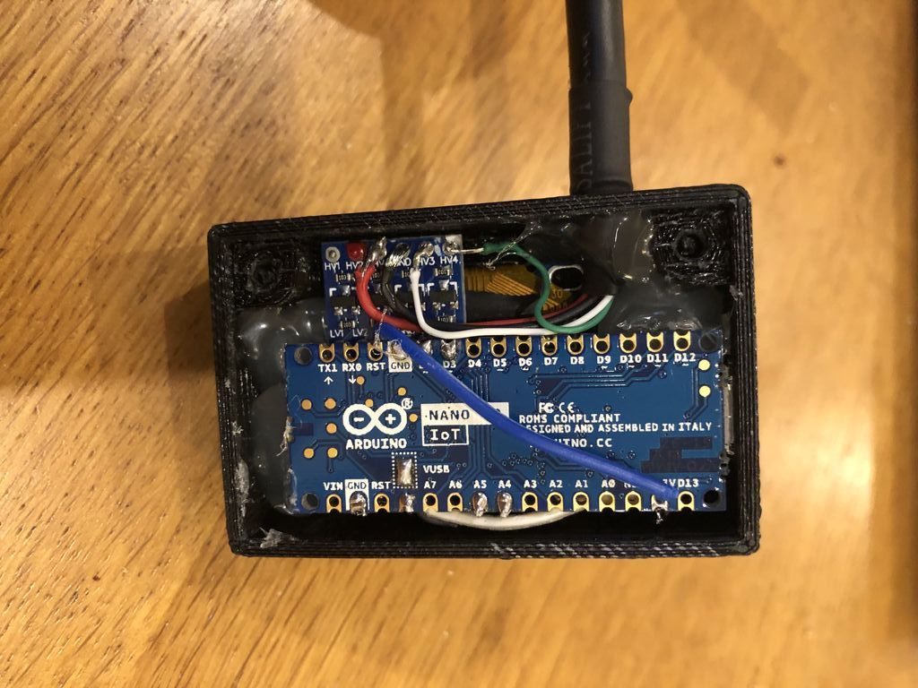
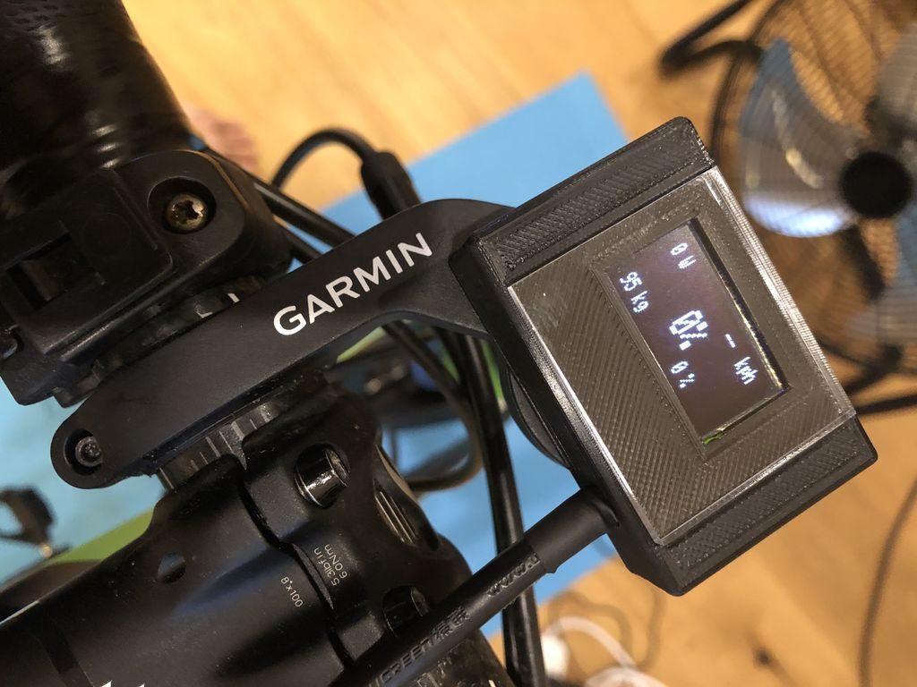
With this data in hand, the Nano controls a linear actuator using an L298N-based driver board to raise or lower the bike’s front end. The derived bike angle is sensed via the Nano’s built-in IMU, providing an elegant closed-loop system. Additionally, the incline is shown on a 1.3″ I2C OLED display that serves as a mini dashboard while Ockendon cycles.
November 25th, 2019 at 03:03:47
Are you at all worried about the rear drop outs?
November 25th, 2019 at 08:28:33
Great Idea. Would this work on the origianl Neo 1? Also, would it work on Zwift?
November 25th, 2019 at 09:48:10
Hi, thank you for the generous write up. It has been a really interesting project and has become part of my training (I rode 40km with it last night).
This will definitely work with the Tacx Neo and Neo 2 as they also broadcast the speed and power metrics over Ant+.
It works great with Zwift (and anything else that the trainer works with) the software needs to have the same wheel circumference and rider weight as the OpenGradeSim.
The rear dropouts on my disc brake bike sit on smooth axle adapters of the trainer. A light grease and less than super tight – fully accept this is not how they are meant to move but not a mark on the anodisation after many hours makes me think it’ll be ok.
November 26th, 2019 at 13:44:56
Matt, really impressed with this and have added this to my winter “to-build” list of fun projects. I’m on an original Neo 1 model and the old style quick release. I’m not too concerned about the wear on the dropouts… I’ll come up with a solution for the wear on the dropouts.. probably a simple bearing design as mentioned in other places.. If would wouldn’t mind, sometime if you are on Zwift, could you maybe shoot a video at how quickly it reacts to the gradient changes? I’d be very interested to know this. Again, great hack! “Ride-On!’
November 29th, 2019 at 20:49:44
I’m working on the drop out issue, will add something to the instructable soon. Simply adding some shims to the QR adapters, mounting a bearing on them to fit the drop outs on my through axle bike and then securing with an over size QR skewer. The QR adapters take a standard 61800-2RS bearing almost like they were machined to fit (5mm inside, 19mm outside and 5mm wide). At the min. this needs the gears to be re-indexed so I’m designing a replacement for the drive side of the correct offset.
Kerryjapan – happy to post some video – It sure isn’t as quick as the Kickr Climb with the £20 linear actuator but I’m loving it on the mountain passes.
December 1st, 2019 at 12:33:44
Incredible idea!
A couple years back I purchased a Proform TDF 5.0 trainer for off season training, but unfortunately it has proved to be somewhat of a lemon.The trainer has a tilt and resistance system to simulate the changing topography driven by google maps. sadly, this otherwise smart looking trainer, has an Achilles heel in its electronics.
I’ve been toying around with the idea of ripping out all the electronics and trying something similar to what you’ve accomplished; very impressive by the way!
I ran across a developer in Argentina that created a product by the name DataBridge, which allows owners of my brand trainer to connect via ANT+ to Zwift! I enjoyed Zwift for as season, but after two console failures (one, a failed solder joint, and the second, a faulty touch screen), Presently I’ve tie wrapped the magnetic resistance in a fixed position until I can formulate an Arduino fix..
It seems easy to drive the 5 lead DC stepper motor. to advance the resistance. I wasn’t a big fan of the tilting, especially on the downhill runs, as it places you in a far forward leaning position with little to no resistance on the pedals to take the load off the hands. Tilting back on climbs on the other hand, was more ergonomic.Having the ability to limit the forward tilt is appealing.
I’m 62 with around 30K miles on the road and trainer, and don’t like the idea of stopping now. I’m certainly glad I ran across your post. I’m not electronics savvy, but the opensource of Arduino seems promising.
Thanks for sharing your awesome Idea! Its given me the needed boost to create a plug and play unit that any owner of the equipment I have can build themselves, and as one poster said “Ride On”
Cheers
December 14th, 2019 at 10:10:31
Sounds like a great project – the things around the house I’ve fixed are more satisfying that the new ones! Some great posts on the instructable about ANT+ by the way.