Add an Arduino-based tachometer to your CNC router
In order to get a good cut with a CNC router, the cutting tool speed needs to be properly set. Since his CNC didn’t come with RPM feedback, Troy Barbour came up with his own solution using an Arduino Nano along with an IR emitter/sensor pair.
The spindle was set up with a single reflective surface, enabling it to sense one pulse per revolution that is sent to the Arduino at up to up to 30,000 RPM. To ensure accurate measurement, the device was programmed using an interrupt, meaning that if another process is running, it will temporarily drop what it’s doing and count the incoming pulse.
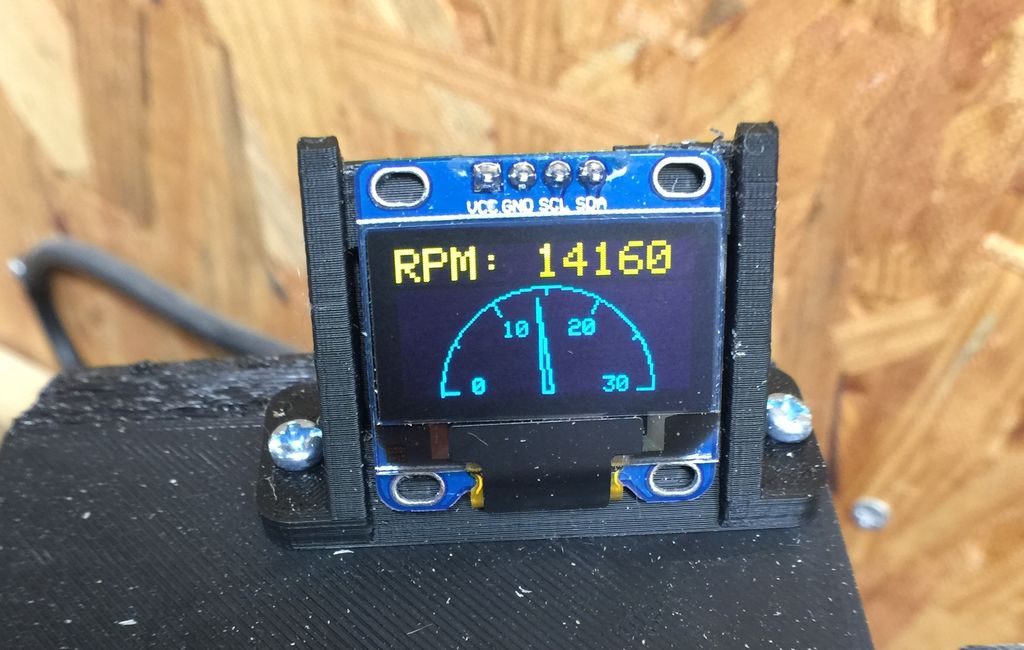
RPM is displayed on a tiny OLED screen, which shows both an RPM number as well as a dial indicator for quick reference.
Build an optical RPM indicator for your CNC router with an Arduino Nano, an IR LED/IR photodiode sensor and an OLED display for less than $30. I was inspired by eletro18’s Measure RPM – Optical Tachometer Instructable and wanted to add a tachometer to my CNC router. I simplified the sensor circuit, designed a custom 3D-printed bracket for my Sienci CNC router. Then I wrote an Arduino sketch to display both a digital and analog dial on an OLED display.
You can see it in action below, and find build instructions and code on Barbour’s write-up.