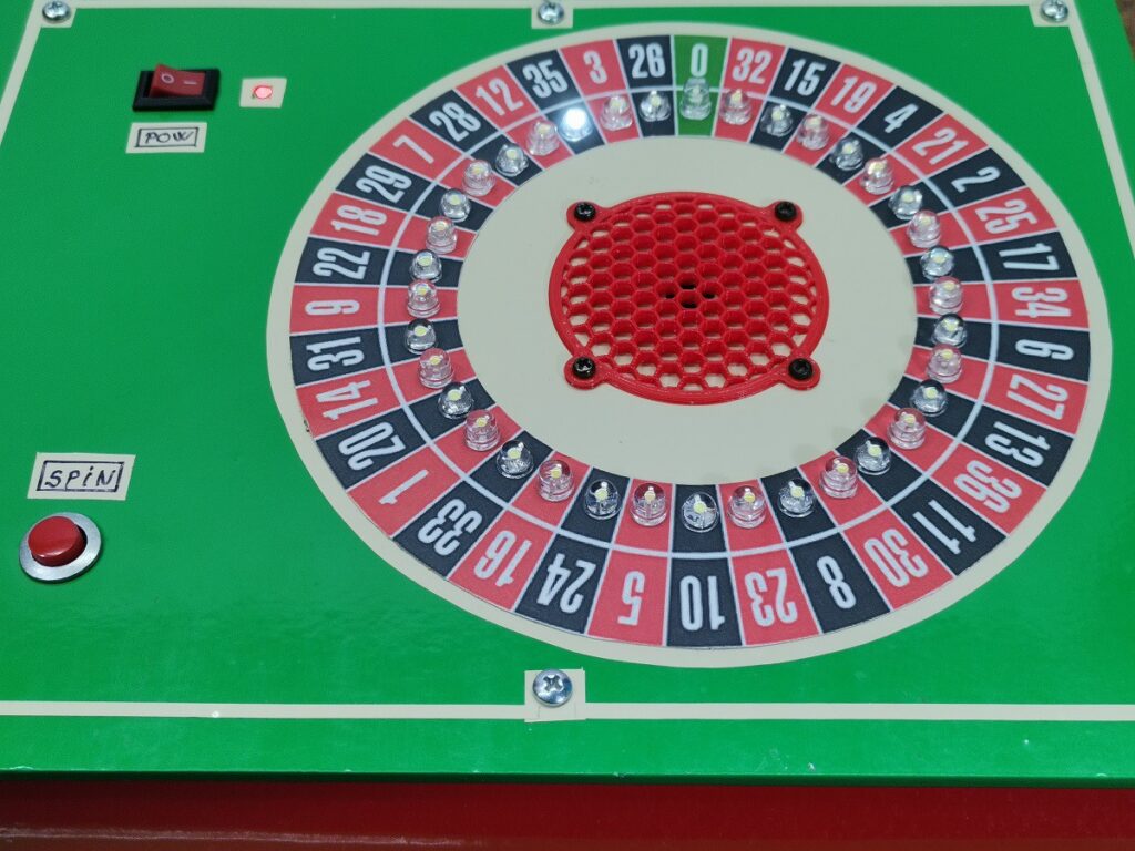
Digital European roulette wheel takes advantage of charlieplexing

Roulette is one of the classic casino games, along with poker, blackjack, baccarat, and craps. There are two popular versions of roulette: American and European. The American version features an additional zero (green) pocket and the numbered pockets in a different arrangement. Mirko Pavleski built a digital European roulette wheel and used charlieplexing to drive all 37 LEDs, speaker, and button with a single Arduino Nano.
Multiplexing is a common technique for driving a grid of LEDs and it works by setting the rows and columns to either HIGH or LOW. An LED will only turn on if its row is HIGH and its column is LOW (or vice-versa, depending on the LED’s orientation). This means a microcontroller can control a number of LEDs equal to the number of column pins multiplied by the number of row pins. An 8×8 grid (16 pins) can therefore contain 64 LEDs.
Charlieplexing is more complicated, but allows for far more LEDs. That number is equal to the number of pins (N) squared, minus the number of pins (N). So with 16 pins, a microcontroller could control 240 LEDs (16^2 – 16). This works because of a pair of pins can control two LEDs (one for each flow direction), and two pairs can control their two LEDs each plus another pair. That extends, resulting in a schematic that looks like a pyramid. Jeremy Cook has an in-depth explanation of charlieplexing here if you want to know more.
Pavleski took advantage of charlieplexing to drive all the LEDs on their Roulette wheel, which needs one LED for each pocket. They used an Arduino Nano, which has 22 I/O pins. As we can see from the formula in the previous paragraph, 37 LEDs require only 7 I/O pins when charlieplexed. That left plenty of pins available for the button and the buzzer.
The game operation is straightforward. When the player pushes the “spin” button, the LEDs illuminate in sequence before landing on a pseudo-random pocket—ideally the one where the player placed their bet.